For the longevity and safe running of ball bearings and roller bearings, it is important that these are completely are completely error-free. In order to detect production defects safely and reliably, automatic 100 % inspection directly after production, the “state of the art” solution is required. The inspection takes place automatically, without manual intervention and contactless to avoid any bearing damage.
Active Inspection, a leading US system integrator for image processing systems, has developed an inspection system for ball bearings based on Chromasens’
3DPIXA 3D stereo line scan camera that is characterized by high flexibility and high speed. The system can be used for almost all types of ball and roller bearings by simple teach-in and detects even very small defects up to a size of 3 μm. “The analysis of the error catalogue and the large variety of types of roller, ball and sleeve bearings to be inspected very soon showed that only a tailor-made inspection system can meet all requirements,” says Arun Dalmia, Managing Director of Active Inspection. For the system concept, it was necessary to combine the high speed of the parts with the detection of very small defects. “And in order to carry out dents and flatness checks, a reliable and precise 3D system is required,” continues Arun Dalmia.
The inspection system is designed to inspect the bearings directly in the production line, with each part being inspected from both sides. Up to 80 parts per minute are produced and inspected directly at the same speed. The defects to be detected include missing balls, rollers and needles, missing pins, incomplete imprints (ink) and various types of scratches, as well as dents, press defects and flatness control.
Important criteria for the system concept were the inspection of the bearings on both sides, the high speed and the required accuracy. A particular challenge was the reliable detection of press defects. “These can occur when the individual bearing components are pressed together,” explains Arun Dalmia. “Since these errors have very small width and height extensions and are also very flat with a shallow depth of only 100 μm, the detection requires precise 3D data. The metallic and also partially polished surfaces of the bearings must be checked for defects just as the more matt parts of the bearings.”
After extensive preliminary investigations, the 3DPixa from Chromasens was selected as the 3D camera system because it meets all the criteria required for this inspection task:
- High speed of up to 29 kHz / seconds for the 80 parts / minute
- High resolution of 15 μm (lateral) and 5 μm in height;
- Simultaneous acquisition of color images and 3D data.
But the 3DPixa also offers another important advantage as Arun Dalmia explains that 3D recording of polished surfaces is only possible through the use of diffuse lighting. The high lateral resolution of 15 μm is required for the detection of small defects. The high height resolution of 10 μm is necessary for the reliable control of the flatness.
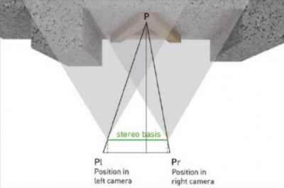
The 3DPixa Dual 15 μm with 15 micrometer lateral resolution and a detection range of 105 mm in comparison to a typical stereo vision system, in which two lenses are positioned horizontally against each other, offset area scan cameras are used, the 3DPixa uses a novel method for imaging 3D surfaces with two 7,300 x 3 (RGB) line scanners that combine stereo and line scan camera technology as well as 2D color and 3D measurements. To record 3D data, the stereo system uses two line scan cameras that are firmly connected in a housing. Light from the same object point is captured simultaneously with both the right and left cameras of the line scanner. As the object moves, it creates stereo images from which the 3D information is calculated by comparing a set of points in an image with the same set of points in the second image. By comparing the two images, the relative depth information can be calculated and produced as a so-called disparity map, in which objects closer to the stereo camera system have a greater disparity than those further away.
High end graphics cards are used to calculate the 3D data from the stereo images at high speed.
Inspection System Structure
The inspection system consists of a special conveyor belt that enables image acquisition of the ball bearing from both sides. After image acquisition of the top side of the bearing with the first camera station, the bearing is inspected with a special mechanism and comes to lie rotated 180 degrees on a parallel lower belt. With this second band the bearing becomes the second camera station and the underside of the bearing is picked up and checked.
Fast Learning Of New parts with Interactive Recipe Editor
A test recipe is stored for each type of ball bearing. More than 100 different types of bearings are tested and the catalog of parts is constantly growing. Creating the recipe with the existing methods would have been too time-consuming for the operators of the system. In particular, the optimization of the parameters for error detection would have required several passes of the same part, each time adjusting the parameters until the errors on the part are reliably detected. In an in-line inspection system, this involves a great deal of effort and would also mean line down-times. Active Inspection has developed an interactive recipe editor that significantly simplifies the creation of recipes for the customer. With this recipe editor it is possible to create and optimize the recipe on the basis of only a few good and bad parts.
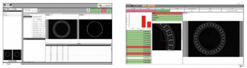
The customer enters the parameters of the new recipe based on the stored images of these sample parts. The recipe editor immediately calculates the new results based on the saved images and displays them dynamically. This allows the operator to very quickly set the parameters for a new part to the optimum value without having to transport the part through the system again.
The inspection system is integrated with the customer’s production plant controller from Siemens. The PLC informs the inspection system which part is to be inspected next with the corresponding recipe for the part loaded and activated. Production typically takes place in batches of the same type. The PLC also informs the inspection system when a part enters under the camera and the image acquisition has to be triggered.
When the inspection of a part is completed, the inspection system sends the result (good or bad) to the PLC, which then initiates the appropriate procedure, either ejection or bearing transfer to the next processing step.
For more information: www.chromasens.de
Tags: 3d vina, Fast and Precise Stereo Line Scan System Checks Ball and Roller Bearings, hiệu chuẩn, hiệu chuẩn thiết bị, máy đo 2d, máy đo 3d, máy đo cmm, sửa máy đo 2d, sửa máy đo 3d, sửa máy đo cmm