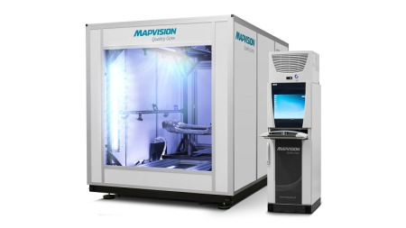
Mapvision is changing the game by introducing a new Mapvision Quality Gate unit which can measure absolute coordinates without any help from a CMM. The rate of change is accelerating in manufacturing industry and especially in the car industry. Product cycles are getting shorter and shorter. New materials and new kinds of components are being introduced every year. The variety of models and customization options is exploding. All of these factors are increasing uncertainty in the manufacturing processes and making it increasingly important that new production lines and updates to existing ones get ramped up quickly and reliably.
 100% In-line Quality Inspection Without CMM Support
The only solution for introducing new products rapidly without excess scrap and quality problems is to have 100% in-line measuring that provides complete visibility to the quality being produced. So far this visibility has been achieved with CMM-assisted in-line measuring systems that are ultimately slowed down by the requirement of running the parts through a CMM before any process adjustment can be authorized.
Traditionally, in-line measurement systems have been tethered to CMM machines. To get production line adjustments authorized, a round of CMM verification has been required to verify the reported in-line data. This has largely left undelivered the full benefits of in-line measurement, such as faster ramp-ups. Even for stable production, the constant correlation checking between two completely different types of machines using different measurement methods is a non-value adding procedure.
Mapvision has taken steps to make its Quality Gate measure absolute coordinates to cut the dependency to any CMM-based data. This new development generates reference points of features independently and proves the absolute nature of the measured coordinates and uses realistic 3D CAD generated images as its reference. For the second point, we are looking for the VDI 2634-1 procedure to give us the proof.
A 3D CAD model is the ideal reference part since it is by definition the nominal presentation of the part, and the virtual world is actually the only place where true nominal parts can exist. There are a number of challenges related to measuring features in real photographs using synthetic ones as reference. The biggest one is making the 3D CAD world look realistic enough, so that a measuring-grade comparison can take place.
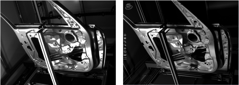
For the realism of the CAD generated images, mastering simulated illumination is the key. The illumination inside a sealed Mapvision Quality Gate system can be controlled completely and simulated accurately. In many cases, good enough simulated illumination can be created with simple rasterization methods. For a truly universal solution with realistic shadows, secondary reflections and such, a ray tracing method is being developed.
VDI 2634-1 Testing
To prove the Mapvision Quality Gate measured coordinates are in fact absolute, a verification method must be introduced. The VDI 2634-1 recommendation is the one best suited for camera-based measuring system verification.
A simulator component has been developed to automate the selection of seven distinct measuring artefact positions for every pairing of Mapvision Quality Gate and the measured part(s), following the VDI guidelines. The simulator selected positions are then recreated in the real environment using an AR-enhanced process involving a mechanical portal fixture with degrees of freedom limited to that of the simulated world to minimize operator influence.
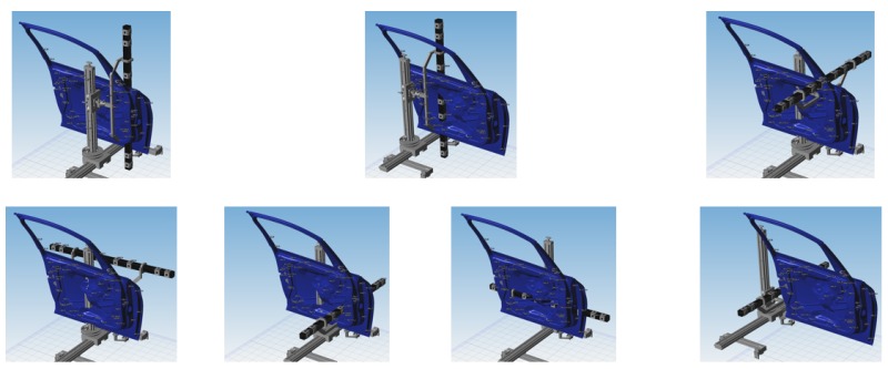
Measured distance combinations between the targets on the artefact are then compared to ground truth values known with a maximum of 5.8 µm uncertainty. The combination of simulation tools and flexible mechanics allows the absolute accuracy verification method to be implemented in negligible time as a part of the delivery process of every Mapvision Quality Gate.
A thorough test procedure like this is only required one time at Mapvision premises before shipping the unit. It practically verifies the design of the sensor configuration, which does not fundamentally change over the lifetime of the system.
Programming of Quality Gate With CAD Referencing
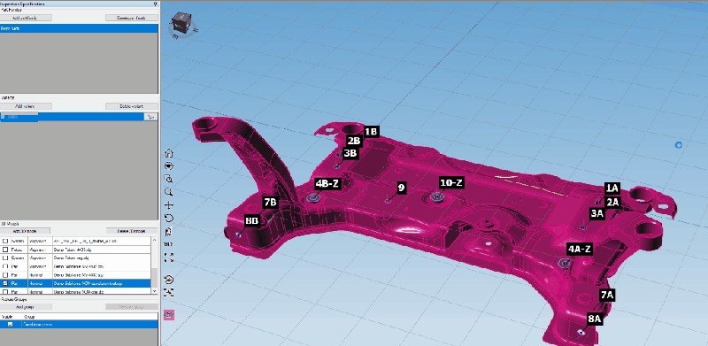
Mapvision Editor Suite is the latest addition to the Mapvision software solutions for visualizing quality. It allows the generation of inspection programs by utilizing 3D CAD model of the part to be inspected along with rendered 2D reference images of the CAD model. Users simply define the features required to be measured on top of the 3D CAD model along with their tolerances. The simulator automation generates the machine vision programming automatically. As the final step the rendered reference images are swapped in.
For more information:.www.mapvision.fi
(The above article was compiled from postings on the Mapvision blog authored by CTO Kosti Kanna)
Tags: 3d vina, hiệu chuẩn, hiệu chuẩn thiết bị, Mapvision Quality Gate Goes Absolute, máy đo 2d, máy đo 3d, máy đo cmm, sửa máy đo 2d, sửa máy đo 3d, sửa máy đo cmm